
Place the ECU with the SMALLER black plug facing you on the left.
Remove the 5 case screws and open the lid.
Please follow the pictures below for the wiring connections.
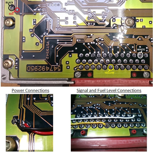
Please note: The YELLOW wire simulates the fuel level signal to the ECU from the BECM. This is not needed if the ECU is going back into a P38 with a working BECM.
Finally, remove the screws holding the circuit board and using the red plug to lift, lift the board up and then backwards as it is 2 circuit boards connected via large ribbon cables to make a clamshell style configuration.
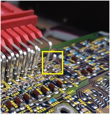
Now locate the signal pin highlighted in the yellow box in the next picture, cut it and bend it back.
For reference this pin is the same pin as we connected the white wire to, just on the opposite side of the board.
Now you can synchronise the ECU to the emulator using a nanocom, hawkeye or other dealership level diagnostic tool.