
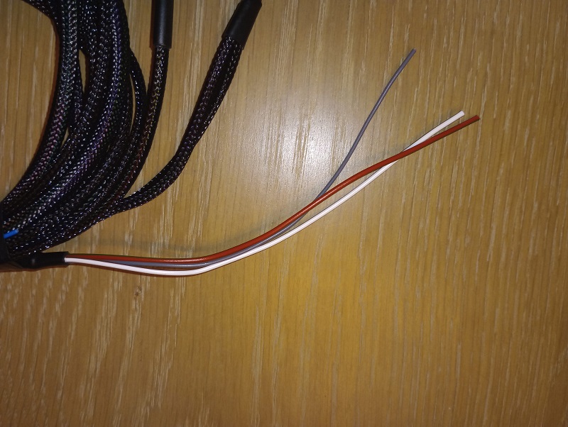
Wiring Colours:
Red Wire: Ignition live from key switch. Connect via a 7.5a fuse.
Grey Wire: RPM Signal from ECU for tachometer.
White / Brown wire: Oil Pressure warning light. This warning light is ground switched
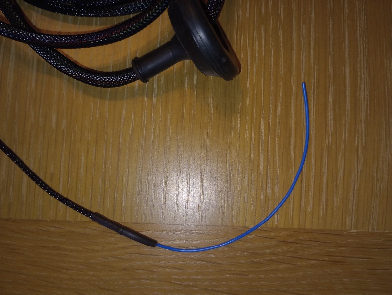
Blue Wire:
Fuel pump relay activation wire.
This activation wire is ground switched.
See the footnotes at the end of page.
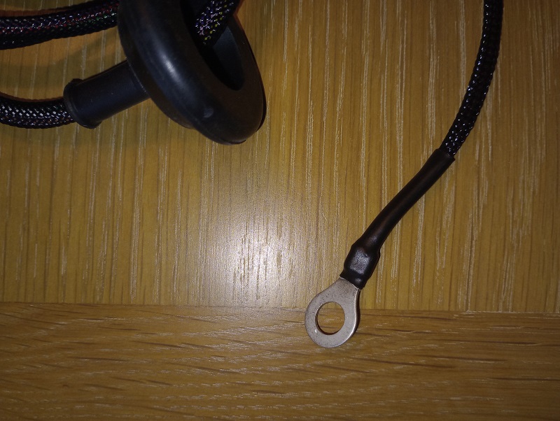
Ring Terminal:
Connect to a good solid ground.
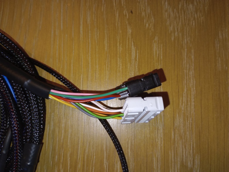
ECU Pin Connectors:
These need to be fitted into the ECU connector housing.
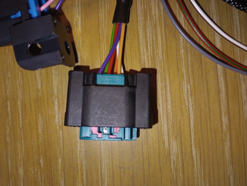
Throttle Pedal Connector BMW:
Plugs into the throttle pedal.
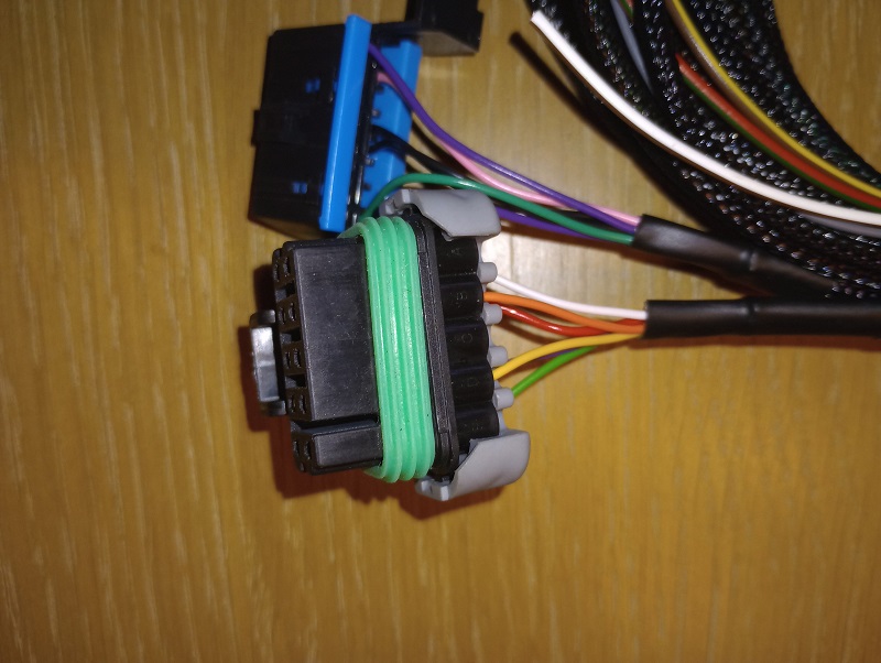
Throttle Pedal Connector Transit:
Plugs into the throttle pedal.
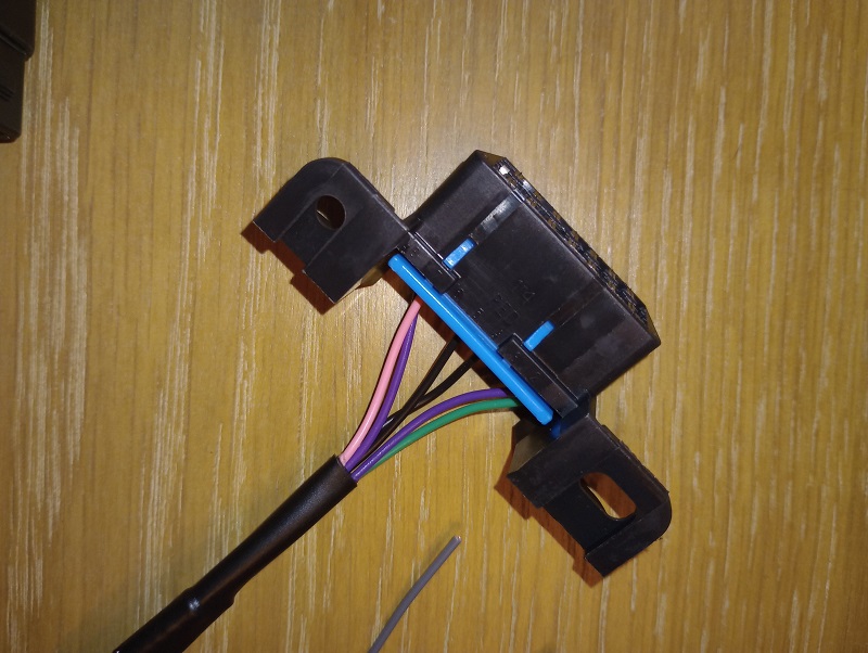
Throttle Pedal Connector Defender:
Plugs into the throttle pedal.
OBD2 Connector:
Mount where you wish.
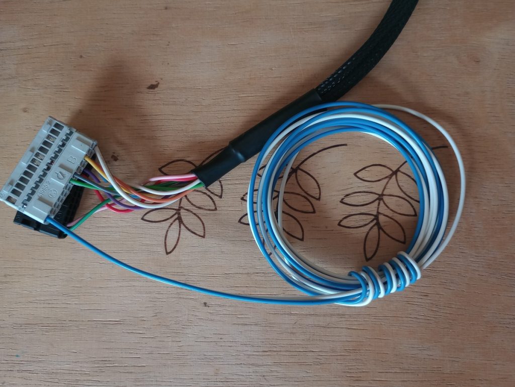
Optional Can Bus Loom:
Blue – Can High
White – Can Low.
Connect where required.
Main Power Relay and ECU Power Feeds.
It is assumed you will be using the blue main relay, the small main fuse box and the ECU connector from the donor vehicle. it is suggested this is removed from the donor vehicle at the same time as the engine wiring harness as the main relay on / off switch from the ECU is actually on the engine loom connector.
A brief explanation of ground switching.
Ground switching is when the electrical circuit is completed by switching the ground side of the of the circuit. In our case, the ECU switches the ground on and off on the warning lights and the fuel pump relay to activate and deactivate them. Please see the schematics below for an explanation.
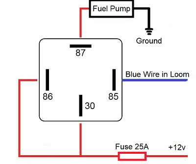
Fuel Pump Relay:
It is anticipated that you will be switching the original fuel pump relay from the vehicle which will in 99.9% of cases be ground switched so check the wiring diagram.
In the event you do not have a fuel pump relay and need to install one, the schematic on the right will suffice
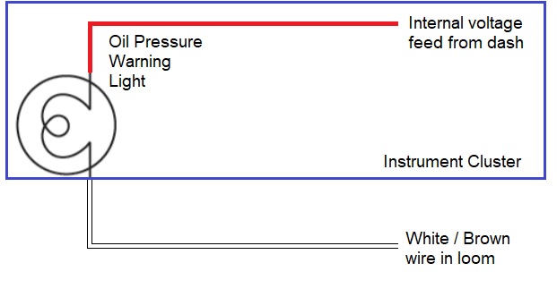
Oil Pressure:
The Oil Pressure warning light has an internal voltage feed from the instrument cluster they are located in.
Wire up the loom as shown to the instrument cluster connector or in a suitable place in the original wiring loom going to the instrument cluster.